Nutron Star free-precession simulation | MATLAB

Source code in MATLAB

clf
R=1000;r=1;phi=45;theta=5;omega1=1;omega2=0.023;
%%%phi/theta are inclination of precession
%%%and self_rotation respectively, omega1/2 are angular velocity of
%%%self_rotation and free_precession respectively
x=@(t)(R+r*cosd(phi)*sind(theta))*cosd(omega2*t)+r*sind(phi)*cosd(omega1*t)*cosd(theta);
y=@(t)(R+r*cosd(phi)*sind(theta))*sind(omega2*t)+r*sind(phi)*sind(omega1*t);
z=@(t)r*cosd(phi)*cosd(theta)-r*sind(phi)*sind(theta)*cosd(omega1*t);
ezplot3(x,y,z,[0,1000],'animate')

The simulation result

CB908695-967C-4A0E-88C3-8664F4745AF9

The problems merit further research

  1. what’s the relationship between precession radius R and the profile of binary system?
  2. How to demodulate this signal with free-procession by HHT analysis?
  3. For specific value of parameters, the signal has been found a drift of peak, does it have something to do with QPO?

Presentation on mode-mixing problem of EEMD | scripting only :D

Introduction

This is a work log of my recent research on Hilbert-Huang Transform [HHT], only part of it. Due to the fact that I was lazy about blogging, so the complete work log for HHT is not on the schedule of posting. This post is mainly about the mode mixing problems, including the questions of what it is, how it should be solved, and so forth.

Mode-Mixing Problem

As the essential purpose of Empirical Mode Decomposition [EMD] method is to decompose the signal to many IMFs with different range of frequency. From low frequency to high frequency, we can designate them as different mode. So if the situation occurs, that the frequencies in different range mixed in one signal or in one IMF, this is called the mode mixing problem. In this case we need a process to pick the specific mode or say to separate the different mode. It should be mentioned that the basic EMD method fails in this problem for some reason which I’m not gonna describe here.

Ensemble Empirical Method Decomposition [EEMD]

In 2009, Huang propose a method to solve the mode-mixing problem by adding white noise to the target signal. With the relatively high frequency white noise added, the proposed EEMD is developed as follows¹:

  1. add a white noise series to the targeted data;
  2. decompose the data with added white noise into IMFs;
  3. repeat step 1 and step 2 again and again, but with different white noise series each time; and
  4. obtain the (ensemble) means of corresponding IMFs of the decompositions as the final result.

well, it should be noticed that you add white noise once, you do the EMD then, you only get a series of IMFs with white noise you added. As step 3 and step 4 proposed, we need to repeat process of adding white noise and doing EMD, we obtain many different series of IMFs then, the amount of series depends on the ensemble number you set. Ensemble number means how many times you added the noise to the data. When you calculating the means of corresponding IMFs, the lager ensemble number you set, you can wipe the noise from the signal completely. As showed in these figures, with more times I added white noise, the signal here is outstanding from the white noise. In this case, the expected signal appears. Nevertheless, in the process of EEMD, the white noise or say noise, are not possible to exclude completely. So in practical situation, we concerned about the signal-noise ratio [SNR].

As you see in this figure, with the ensemble number up to one thousand, the SNR is good enough for the physical analyses. the high frequency signal constrain in the middle of the whole interval, which is exactly the signal I’ve constructed. So in the process of decomposing the the signal, it’s important to distinguish the signal with physical meaning from the noise. So the question here is Which components of a signal are noise?

Well, as the lower amplitude of the noise you added, the more significant the signal was. FYI the proper low amplitude of noise can raise the SNR. By setting different amplitude (different means statistical expectation different, due to that the white noise added by random numbers varies by an expectation, amplitude of noise are different in each noise-added process of course.) the specific components of the signal had distinct decrease for same ensemble number. Bang! That’s noise for sure! Because, obviously the signal only agree to the mean value when the ensemble number increase.

Does it mean you can add unlimited low noise to the signal to obtain best SNR? Absolutely not! The fact is that if the added noise amplitude is too small, it may not introduce the change of extrema the EMD relies on somehow¹. So here is the STRATEGY of adding white noise: add the amplitude 0.2 times the standard deviation of the original signal, and set the ensemble numbers large enough for acceptable SNR, which I recommend 1000 times at least.

Last but not least, I post two decomposition result of EMD and EEMD for comparison as follows:

left:EMD mode-mixing result; right:EEMD mode-mixing (solved) result
EMDsimulationEEMDsimulation

Reference

  1. Ensemble empirical mode decomposition: a noise-assisted data analysis method. Advances in adaptive data analysis, 1(01), 1-41.

A Review of calculating Energy flux for HXMT | Physics background in a nutshell

Abstract: HXMT, Hard X-ray Modulation Telescope is the project I’ve been working on. The major purpose in this period is to calculation the energy flux of instruments on satellite. My last work log introduced the numerical calculation tool of my work, Mathematica, which maybe not as elegant and cool as what c++ or python does, but it turns out that works at all. This log mainly focused on the relevant physics stuff concerned in this work, which contained spectral model of astro-sources, interstellar absorption model, effective area of instrument.

RADIATIVE PROCESSES IN ASTROPHYSICS

As my last log mentioned, approximately half of my work first focused on the INTEGRAL catalog. obviously, the first thing before calculating the HXMT energy flux is verify the method and spectral model are trustworthy. Well, the INTEGRAL provided the general reference catalog, of which I used version 39. In the catalog, there are 4 columns reported the value of calibration energy flux calculated by XSPEC. (It’s a good idea to post some logs of XSPEC) So, the first step is to calculate the flux in 10-50KeV, 20-60KeV, 60-200KeV with the model parameters given by the site: http://isdc.unige.ch/integral/catalog/39/catalog.html The reported calibration value are given in unit of cgs, so the energy fluxes are in unit of erg\cdot cm^{-2}\cdot s^{-1}, so the flux expression are given by:

\int{\frac{A}{6.24\times {{10}^{8}}(KeV\cdot er{{g}^{-1}})}\cdot E\cdot {{E}^{-\Gamma }}dE}

\int{\frac{A}{6.24\times {{10}^{8}}(KeV\cdot er{{g}^{-1}})}\cdot exp(-E/{{E}_{cut}})\cdot E\cdot {{E}^{-\Gamma }}dE}

those two equation calculated the powerlaw model and cutoff model, in which A refers to normalization coefficient  and \Gamma is photon index. Oops! My logic is a little bit chaotic right now, I should have introduce all the spectral models before calculating the flux utilizing those models. Anyway I’m not tend to list the mathematical expression of powerlaw, high energy cutoff, broken powerlaw, power. 

INTERSTELLAR ABSORPTION

In the content above I didn’t mention that calibration value includes a energy range 3-10KeV, in which energy range the photon is call soft X-ray radiation. The extragalactic radiation of X-ray is dominated by soft X-ray radiation. As the interstellar molecule have the property to absorb the radiation, the soft X-ray radiation must consider interstellar absorption effect.

f(E)=f_{0}(E)e^{-\sigma(E)n_{H}}

where\sigma(E) 
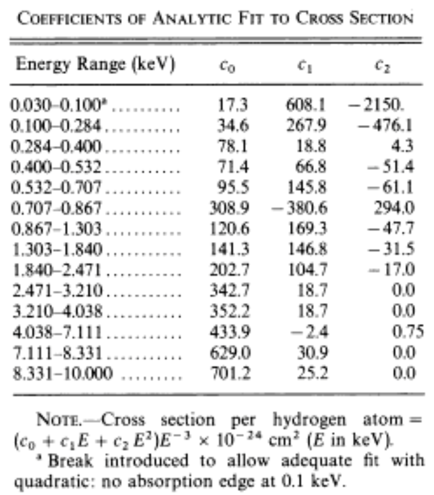
is the interstellar medium cross-section.

there are many version of cross section, but INTEGRAL catalog utilizes Wisconsin Cross-section:

\sigma (E)=({{c}_{0}}+{{c}_{1}}E+{{c}_{2}}{{E}^{2}}){{E}^{-3}}\times ({{10}^{-24}}c{{m}^{2}})

and the coefficients of analytic fit to cross section are given in following table:

Screen Shot 2015-03-12 at 8.49.12 AM

As we can see, the interstellar absorption only happened under the energy of 10KeV. So we can transfer the integration to the following form:

\sum\limits_{i}{\int\limits_{i}{\exp [-({{c}_{0}}+{{c}_{1}}E+{{c}_{2}}{{E}^{2}}){{E}^{-3}}\cdot {{10}^{-24}}\cdot {{n}_{H}}\cdot Af(E)dE}}

Though this log was aimed to introduce the physics regime, but it occurred to me to verifying the reason that Mathematica results had the deviation to XSPEC while considering the interstellar absorption which you have to carry out the numerical integration. So I utilized Python to set a parameter, energy bin, which is the same thing to interval. This parameter partitions the flux range to N sub-intervals.

and here’s the python code:

import numpy as np
import pylab as pl
import scipy
A=10 #normalization coefficient 
nh=0.26 #column density of hydrogen(unit of 10**22atom/cm**2)
c=2.1 #photon index
N=20000 #energy bin=N
x1=np.linspace(3,3.21,N,endpoint=False)
y1=np.trapz(np.e**(-(342.7+18.7*x1+0*(x1**2))*(x1**(-3))*(10**(-24))*nh)*A/(6.24*(10**8))*x1*(x1**(-c)),x1)
x2=np.linspace(3.21,4.038,N,endpoint=False)
y2=np.trapz(np.e**(-(352.2+18.7*x2+0*(x2**2))*(x2**(-3))*(10**(-24))*nh)*A/(6.24*(10**8))*x2*(x2**(-c)),x2)
x3=np.linspace(4.038,7.111,N,endpoint=False)
y3=np.trapz(np.e**(-(433.9+(-2.4)*x3+0.75*(x3**2))*(x3**(-3))*(10**(-24))*nh)*A/(6.24*(10**8))*x3*(x3**(-c)),x3)
x4=np.linspace(7.111,8.331,N,endpoint=False)
y4=np.trapz(np.e**(-(629+30.9*x4+0*(x4**2))*(x4**(-3))*(10**(-24))*nh)*A/(6.24*(10**8))*x4*(x4**(-c)),x4)
x5=np.linspace(8.331,10,N,endpoint=False)
y5=np.trapz(np.e**(-(701.2+25.2*x5+0*(x5**2))*(x5**(-3))*(10**(-24))*nh)*A/(6.24*(10**8))*x5*(x5**(-c)),x5)
flux=y1+y2+y3+y4+y5 #unit of erg/cm^2/s
print flux

It turns out that XSPEC utilizes N\approx 120 and Mathematica’s N\geqslant 10000

INSTRUMENT EFFECTIVE AREA

Instruments have different matrix responses for different photons in various energy. Till now we have considered the interstellar absorption, spectral and here’s another parameter we should integrate with, that is instrument effective area.

{D}=P(E) \times F(E)

where D is observed value, F is the spectrum we knew, P is the matrix responses. For flux we care about, we can calculate the integration:

{flux}=\int{\text{area of instrument}\cdot \sigma{(E)}\cdot{f}(E)dE}

 integral-effective-area


Those three aspects are in priority list of my recent work, I’ve introduce the basic physics behind it. For more information of HXMT, please visit the site: www.hxmt.cn

Mathematica | A brief log of my recent work

“Calculation of energy flux in High energy Satellite” is my recently work on INTEGRAL catalog. My goal is to calibrate the emitting model and the interstellar absorption model in X-ray energy range. While the model is convincing, I can boldly utilize those models on HXMT catalog for estimation. The following notes are focused on Mathematica which I used to produce the data analysis.

  • Data Import/Export

Mathematica can read many types of data file, like .txt .dat .fits (It’s ok for read, but normally the capacity of  FITS file are about 10MB, so it’s not ok for program running with such a huge burden), especially for large group of data analysis, this proper of mathematica is very useful. When talked about the fits file, there is a little trick I want to note down that I can use the Export function in fv tool to export the specific rows and columns with .txt for data analysis, instead of running the whole FITS raw data. Here’s the code for Importing files:

Import["complete path of your file","Table"]

I import data as table like {{1,2},{44,63}}. What is important to notice is the path syntax. For example, my OS X system have to start with a slash”/” and end up with file name, NO slash in the end.

eg. Import[“/Users/tuoyouli/Desktop/data.txt”,”Table”]

What’s next is exporting file which is similar with Import syntax.

Export["complete write path",data,"Table"]
eg. Export["/Users/tuoyouli/Desktop/HXMT flux/HEcounts.dat",Table[{b[[i]][[2]], b[[i]][[3]], a[[i]]}, {i, 1, Length[a]}], "Table"]
To explain this code let’s move to next section about reorganize data.
  • Data Regroup

The previous Export code include a data reorganize part:

Table[{b[[i]][[2]], b[[i]][[3]], a[[i]]}, {i, 1, Length[a]}]

while a,b are two-dimensional data group like {{1,2,1},{3,4,3},{5,6,5}}, the b[[i]][[2]] is a coordinate that can pick the specific element of the group b. And based on this, you can pick up the specific elements in different data group and then reorganize them by code Table in anyway you like. Huzzah! Another interesting normal usage about reorganization, is to combine two lists on plotting. When I want to plot how groupA depends on groupB, I can write down this code:

ListPlot[Transpose[{A,B}]]

of course, listA and listB must in same length.

  • Numerical Calculation(!)

For this section is the key function for Mathematica. I was told the somebody believe the Calculation Physics is the third fundamental part of physics, the other two are theoretical and experimental physics. Wow, that’s huge! Anyway here’s the numerical calculation which can give out the numerical results instead of analytical results. So when talk about Numerical, two things occur to me. One, numerical integration. Two, fitting and interpolation values. For numerical integration in Mathematica, I can simply use the code NIntegrate[], this code contains different numerical integrate method like Monte Carlo. (for more detail read on NIntegrate Method) Another stuff is interpolate value for a experimental separated data to a curve or line.

eg. Interpolation[data,InterpolationOrder->3,Method->Spline]

This a 3-order spline to interpolate the data, also there are plenty of numerical method for interpolation. (Read More)


So, perhaps in the following career I don’t have much chance to use Mathematica, because Matlab takes the lead, you don’t really want to use the different syntax with people around you. But Mathematica is so elegant and so easy to use, this work was based on Mathematica which help me get through all the obstacles. And this work log may at least not be nonsense.